How-To: Make a Raspberry PI Based DIY Automated Irrigation System
In this post, I will show you how to build an automated irrigation system using a Raspberry PI. It waters my garden automatically every 24 hours. And I can even control it over the web for on-demand watering. I will walk you through the three main components of this system: the plumbing, wiring the Raspberry PI and programming it.
I live in an apartment complex and like any average apartment dweller, I and my wife have built ourselves a little balcony garden. Because who doesn’t like waking up to a little bit of green, right? But, the flip side to keeping plants is that your travel plans are affected. In the past, we have tried more traditional options, with varying levels of success. Sure, you can leave a key with a helpful neighbor, but that might not be an option for everybody. We recently moved to a new house and did not have anyone to rely on, when we decided to go on a week-long holiday. In all the planning leading up the to trip, we almost forgot about this problem. About a week before the trip, we realized that we had no backup this time around. So I decided to do something about it.
We have about 10 large potted plants and 5 small ones. I wanted all of them to survive our week-long trip. I dived right into scoping the problem and designing a system to solve it.
The idea was to have a Raspberry PI control a relay board which could in-turn control a submersible AC water pump.
Parts needed
There can be innumerable ways to solve a problem. I chose my design based mostly on what I already had available in my parts bin. I have included Amazon links here to buy these items:
Electricals
- A Raspberry PI. I used a model 3B+, but even a Raspberry PI Zero W is more than enough for something like this. (Raspberry PI Zero W – Amazon IN, Amazon US)
- An 8G (16G recommended) microSD card. (Amazon IN, Amazon US)
- A 4 channel isolated relay module. (Amazon IN, Amazon US)
- A 5v 2A / 2.5A power supply. (Amazon IN, Amazon US)
- A portable charger with 2 outputs. (Amazon IN, Amazon US)
- Some jumper cables. (Assorted Jumper Wires 120pcs – Amazon IN, Amazon US)
- A 3/4 outlet power strip. (Amazon IN, Amazon US)
- A 12v fan. (Generic PC case fan 80/120mm – Amazon IN, Amazon US)
- A female micro USB plug. (Generic USB plugs set – Amazon IN, Amazon US)
- A plastic box to put everything in.
Plumbing
- An AC submersible pump. (Amazon IN, Amazon US)
- A container that can hold enough water. (Amazon IN)
- A garden hose long enough to cover the required area. (I used a PVC pipe because I wanted a permanent setup)
- Length of drip pipe and connectors. (Amazon IN, Amazon US and Amazon US)
The plumbing
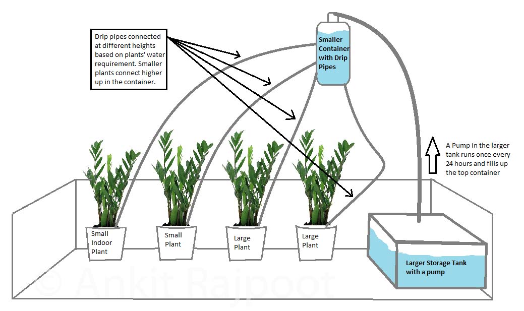
I moved the 5 small indoor plants to the balcony to easy up plumbing. My initial thought was to hang a small plastic container from the ceiling and run drip pipes from it to each of the pots. To control the amount of water that flows through each drip pipe, they could be attached at different heights in the container. This would look something like below:
While this would have worked, there were two main issues with it:
- I wanted something a little more permanent, which I could activate in the future whenever need be.
- A plastic bottle with pipes coming out of it sticks out like a sore thumb. And it’s not good for a healthy WAF score.

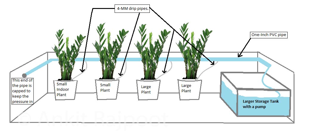
So, I decided on a different approach: Running a 1-inch PVC pipe around the balcony rails, fitted permanently, and connecting the smaller drip pipes directly to it. This eliminated the need to have anything hanging from the ceiling, which guarantees a big improvement in the overall look and the WAF. With the plumbing plan finalized, I took measurements of my balcony and noted everything down. This is what the new arrangement looks like:
I bought the necessary supplies as listed above and quickly fitted everything. Having a few tools helped. I cut the pipes to size using a handsaw and drilled the holes required for drip pipes. I attached the PVC pipe to the balcony using zip ties.
Once I had the plumbing setup finalized, it was time to move on to the second stage.
How to Wire the Raspberry Pi
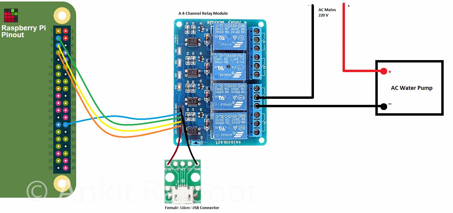
I had a Raspberry Pi 3 Model B+ lying around collecting dust. So, I was planning to use that to implement the brains of this system. Raspberry Pi 3 B+ is a complete overkill for this project and something as humble as even a Raspberry Pi Zero W is more than enough to handle this. The plan was to use the PI’s GPIO pins to drive a relay board which in turn could control the Pump. All I needed now was to wire up the Pi with the Relay and think of how I am going to power both. I came up with a simple circuit as shown below:
A word of caution: Working with AC mains voltages can be dangerous if you are not careful. It might result in damage to your components or an electric shock. Seek qualified help if you are not comfortable doing this yourself.
The above circuit diagram connects physical pins 28, 3, 5 and 7 (GPIO 1, 2, 3, 4 respectively) on the Raspberry PI to pins IN1, IN2, IN3, IN4 on the relay module respectively (It’s a 4-channel relay module). I connected the AC water pump to the third relay. Notice, that the ground line of the mains supply connects to the relay module before reaching the water pump. This is how the relay controls the activation of the pump. The circuit between the two pins is completed when the relay is activated, and the pump turns on. Also connected to the relay module is a female micro-USB connector. This is so that I can power the relay using a standard micro USB cable, such as the one that charges your phone.
You can get detailed information on the pins of the Raspberry Pi by typing “pinout” on a terminal in Raspbian or going to www.pinout.xyz
Note: Relays handle high voltages on one end and are connected to low-voltage sensitive electronics on the other. The recommended way to connect a relay to a Raspberry PI is to use an optocoupler to isolate the two sides of the relay. You don’t see one in the above diagram because this relay module has one built-in. When buying a relay module, make sure to read the description to find if the relay is suitable for direct connection to a logic circuit such as Raspberry PI / Arduino. Most relay modules being sold on Amazon / AliExpress nowadays are.
I made the above GPIO connections using jumper cables and added two 5v power supplies (phone chargers) – one for the Raspberry PI and one for the relay module. I then wrote a small python script on the PI to test out the circuit, substituting the water pump for a bulb.
Once this jerry-rigged proof of concept setup was tested, it was time to put this all in a bigger box and have all the components fixed securely, so they don’t bump into each other and set my house on fire. One of my major focus areas on this whole project was the idea of redundancy and fail-safes. I wanted this system to have a backup for some of the most common failures that I could think of.
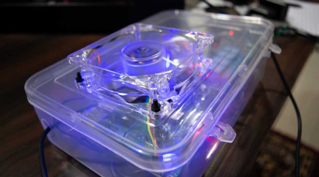
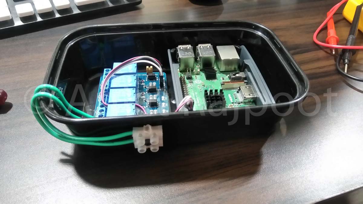
One very common scenario was a power outage. Not that the device could do much if there was a power outage, but I still wanted it to have backup power at least for the Raspberry Pi. This was mostly driven by my fear of the SD card failing due to repeated reboots. So, I threw in an old, but functioning battery pack I had, in the mix and ended up with something looking like this in a new box:
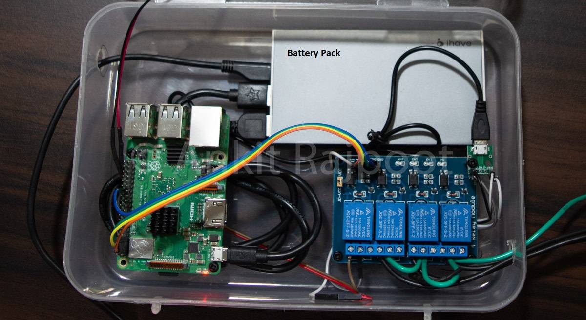
The battery pack has two outputs to connect two devices simultaneously. It was perfect for this purpose as I could connect both the Raspberry Pi and the relay module to the battery pack and did not have to worry about running 2 charging wires into the box. This also made the box a self-contained unit which could run itself for several hours to outlast any power outage. Now, at this point, you know that I have a 4-channel relay module, but the pump is only going to need one relay. So, I started thinking about uses for the other three.
All this while, one thing had me worried: all these electronics in a cheap plastic box could be a recipe for fire. So, I wanted to fix the whole setup outside the home in the balcony. Outside meant more heat during the daytime, which could mean that the Raspberry PI will run very hot in a closed box. So, I wired up one of the relays with a 5v power supply (from the battery pack) and connected it to a CPU fan that I fixed to the box lid. I also cut up various holes using a box cutter to pass wires and also for ventilation.
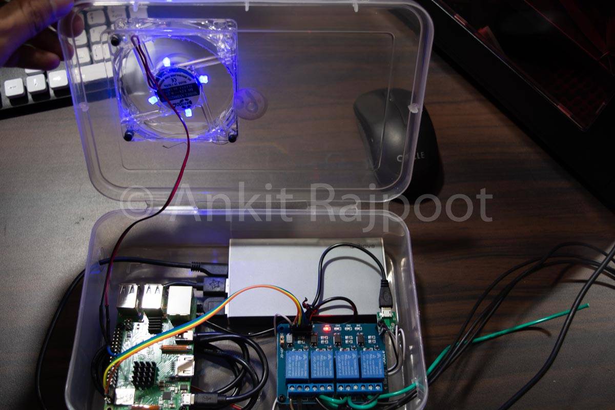
I scripted the fan to turn on when the CPU temperature hits 55*C. Once triggered, it keeps running till the CPU cools down to 45*C. With the fan attached, I now had 3 relays available to handle higher power AC currents. So I decided to hook up a generic extension board to it. The setup looked something like this after everything was wired up:
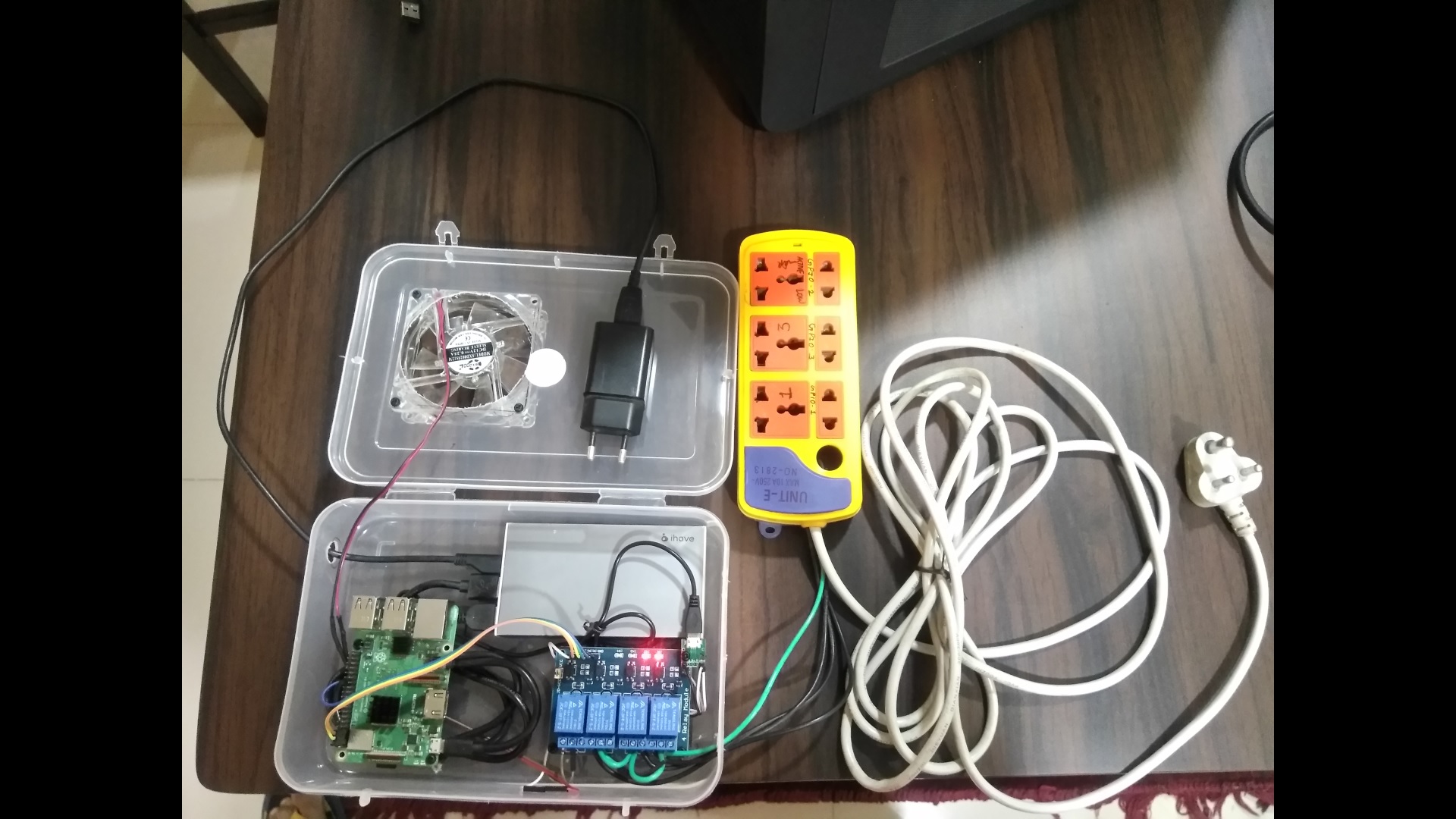
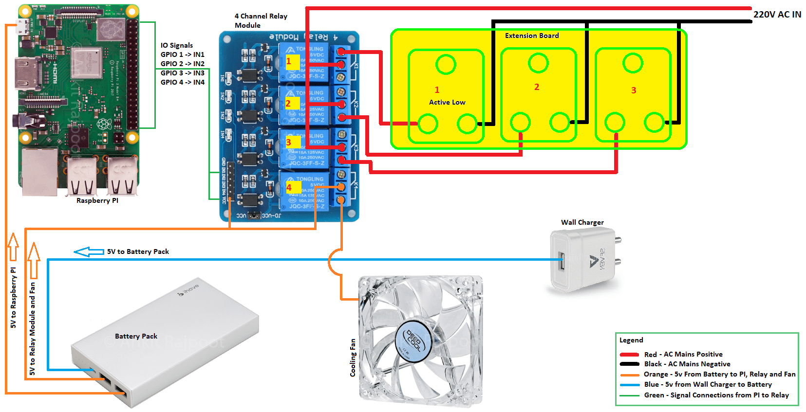
A few things to note in the above diagram:
- I connected the wall charger to Slot 1 in the Extension board. I did not show this in the above diagram to reduce clutter.
- The cooling fan is a typical 12v PC cooling fan running on 5v. This does not harm the fan, it runs slow and is more than enough for the PI.
- Relays 1-3 handle high AC voltage and relay 4 handles 5V DC.
- I wired the setup in such a way that GPIO 1 on the PI controls Relay 1, which controls slot 1 on the extension board. Similarly, GPIO 2, 3 control slots 2 and 3 respectively and GPIO 4 controls the fan. This is to make identification easier during coding.
- The water pump can be connected to either slot 2 or 3.
- Slot 1 is an Active Low slot. i.e. when the relay signal is 0, this slot will have AC power. Other slots are wired the other way around – they only have power when the relay signal is 1 (high). This is a failsafe measure – in case the battery runs out (more on why that might happen in the software section), and the relay board and PI are turned off, the charger is turned on automatically and the system boots up again.
Relays and active-high vs active-low
A relay usually has 3 pins on the AC side. I have numbered them 1-3 in the image below for easy identification:
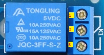
The symbol denoted by K1 to the right of these pins explains how the internal circuitry is wired up in the relay. The white line connects Pin 1 and 2 in the symbol. This is the default state of the relay: pins 1 and 2 are connected when the relay is off. This is the active low state of the relay. If you connect a power source and a load in series to these pins, the circuit is complete and the load would get power.
When the relay is turned on though, the connection between pins 1 and 2 will be broken and instead, pin 2 will be connected to pin 3. Now, pin 2 and 3 make up an active high circuit. Any load connected to pin 3 would turn on only when the relay signal is high.
Note that not all relays follow the same convention, so, before wiring anything up, take a look at its description and the switching diagram.
How to Program the Raspberry Pi
With everything wired up and packed decently, it was time to move to the next stage – the software to control everything. Just like with the electricals and plumbing, I had decided on the scope of the software too and come up with a list of functions I wanted:
- Run the pump reliably: once every 24 hours for 15 seconds.
- Ability to trigger the pump run remotely over the web.
- Keep a log of all times the pump was run in the past and serve that over the web.
Given that I had a little time and only really needed very basic features, I decided to code a solution myself instead of looking for something ready made. This might seem counter-intuitive at first, but it’s not. With any ready-made solution, I’d first have had to spend time searching for it. And even if I found something that fits my requirement, it would most likely have many other features that would add to the complexity and require testing. A tailor-made solution was not only easy to implement, given the relatively easy requirements, but it also fit better and more importantly, I knew the innards of it which provided me the confidence that I can leave this unattended for 10 days.
I decided to implement all the functionality as separate Python scripts. You can find the code and more details on how it works in this GitHub repository GardenPI. Clone the repository to play with the source code:
git clone https://github.com/ankitr42/gardenpi.git
I also wrote some crontab entries to run controller scripts either during boot-up or at regular intervals. For example, the web server and temperature run at boot up. While the pump controller runs every 30 minutes to poll the elapsed time since the last run. To view the crontab commands I used, see the crontab.md file in the repository. You can set up the same crontab on your PI by running crontab -e on a terminal.
I plan on further improving the GardenPI software and make it more generic so that it can fit a wide variety of use cases. At the time of writing this post, the software had the following features.
- Separate scripts to implement services that control pump, battery charger, and cooling fan.
- A small DB that keeps a log of each event happening in the system, such as pump runs, battery charger toggle, and fan toggle.
- The battery charge controller service toggles the charger on/off every 4 hours to avoid over-heating the battery and maintain a charge-discharge cycle. Note that this meant that there was a risk that the battery ran out before the service could turn the charger on. If that happens, the PI and relay would shut down and the slot 1 being an active-low slot, would automatically turn on the charger.
- A small web server that reports the status of each of the above service.
- The web server also allows running the pump on demand with the help of the pump controller script.
Please see the GitHub repository for more information on how you can use the code.
Admittedly, the software took the longest and the most work. It took 2 all-nighters to achieve the bare minimum functionality I was shooting for, work reliably. Managing a full-time job and DIYing on a time-table is hard. Finally, I was able to test the complete set up for 2 days before leaving and it worked flawlessly.
If you have any questions, let me know in the comments below. Or, if you decide to make this, share your story. If this post helped you, please share.