Category: Technology

How-To: DIY Custom Enclosure for Raspberry Pi NAS Media Server

How-To: DIY Custom Enclosure for Raspberry Pi NAS Media Server

In this post, I am building the first version of an enclosure for my Raspberry PI NAS and Media Server setup. It is built using Aluminium angle profiles and a plastic container. This is more like a POC build. It’s functional but not pretty. Eventually, I want to build an enclosure that’s as functional and also looks good in the living room, next to the TV.


Recently, I put my Raspberry PI Model 3B+ to good use as a NAS and Media server using OpenMediaVault and Plex (write-up coming soon). It’s a very good setup for casual file share operations between devices and streaming movie/music/pictures to various devices in the home wirelessly. While the setup did its job, I did not like all the hardware just lying there next to my router. Not to mention, the scalability of this setup wasn’t very good. I have plans to add another 2 TB 2.5″ but didn’t want it to add to the clutter. I also wanted to add some cooling for the PI and more importantly, the disks. So, I decided to make an enclosure that could fit it all in and also had provision for active cooling.

After going through some ideas for the shape for the enclosure, I settled on a cylindrical design. As always, going by the requirements, I ended up choosing aluminum for the internal frame encased in a cylindrical plastic box. I chose aluminum as it’s both an excellent heat conductor and pretty malleable to work with using my limited toolset. The plastic container idea came into the picture, as I could quickly source one from the kitchen. It did have a minor negative impact on the WAF score, but nothing I couldn’t handle with a little persuasion. 😜


Parts Used

  1. Aluminum Profiles (Right Angle) – It’s better to source this from your local hardware store. See images below.
  2. A non-powered USB Hub (Amazon INAmazon US)
  3. A SATA to USB adapter if you are using an internal hard drive (Amazon IN, Amazon US)
  4. Assorted nuts and bolts set (Amazon IN, Amazon US)
  5. Micro USB to DIP connector. (Amazon IN, Amazon US). This is required to convert non-powered USB hub to a powered one. If you are already using a powered hub then skip this.
  6. A Raspberry PI Model 3B+ (Amazon IN, Amazon US)

I yanked the Raspberry Pi 3B+ off of my last project – Raspberry Pi-Based DIY Automated Irrigation System which now happily runs on a Raspberry Pi Zero. As I mentioned in that post, that system did not need all the processing power that the 3B+ has. This project, however, can utilize as much processing power as the Pi can provide and then some.

The Design

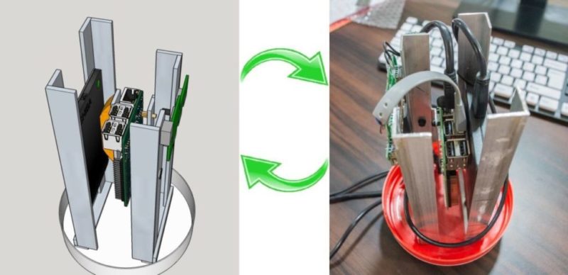
I came up with this simple design for the enclosure in Sketchup. Click to interact and view 3D.

The above design can accommodate two hard drives, a cooling fan, a USB HUB, and, of course, the Raspberry Pi. Right now, I have a 1TB USB drive plugged in. The cooling fan is a 12V 60mm unit which I plan to run at 5V to reduce noise. I initially designed all four vertical aluminum bars to be of equal length. However, I accidentally cut one of the bars too short and liked it that way. So, I decided to make two of them smaller. The two larger bars measure 195mm and the smaller bars measure 180mm. The mounting bars for the hard drives and the Raspberry Pi measure 70mm each. The bottom two aluminum bars which are fixed to the base and hold the vertical bars measure 80mm each. There is enough space between them to fix the 60mm fan.

Here’s an image where I have hidden one of the aluminum bars to better show how everything is fixed.

DIY Enclosure for Raspberry PI based NAS and Media Server

I have made the 3D design available in SketchUp 3D Warehouse. You can either download it for editing in SketchUp desktop or import into SketchUp for Web and play with it there.


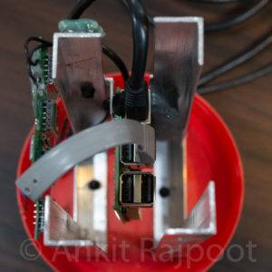
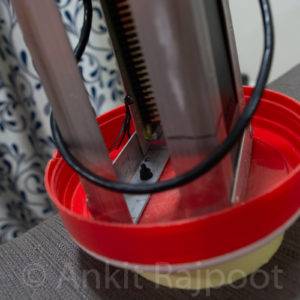
Mounting the Hard Drive

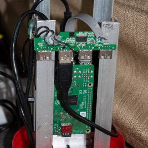
The image below shows the structure of the aluminum frame without the electronics. Notice the two aluminum bars attached to the two larger bars on the right. Those two are used for mounting and they keep the hard drive and the Raspberry PI in place as you can see in the 3D design above. I cut a small piece of sponge shaped like a “D” and glued it to one of the smaller bars to keep the drive firmly pushed in against the larger aluminum bar. The sponge is very useful since I am using a USB HDD with this setup right now which does not have any mounting screw holes. It also helps a lot in heat dissipation by keeping the drive pushed against the large aluminum bars that act as heat sinks for the drive.

DIY Enclosure for Raspberry PI based NAS and Media Server
The aluminum frame without the electronics.


DIY Enclosure for Raspberry PI based NAS and Media Server
Aluminum frame with the HDD in place. The sponge keeps the drive firmly pushed against the aluminum helping in heat dissipation.

If you use a 2.5″ internal drive, you can easily drill mounting holes in the vertical aluminum bars and fix the drive with screws. With internal drives, use a cheap SATA to USB adapter to connect it to the USB hub. Just make sure that your adapter does not require external power to work.

DIY Enclosure for Raspberry PI based NAS and Media Server
Fixing a 2.5-inch internal drive using screws.

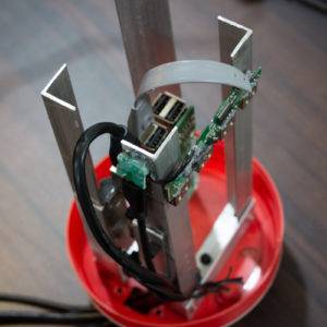
Mounting the Raspberry Pi

The other smaller bar has holes drilled into it to fix two standoffs to mount the Raspberry Pi. This means that the Pi gets mounted between the two drives and will get plenty of airflow when the fan is running. I plan to write a script for the Pi to monitor its own and the drives’ temperature and run the fan if anything gets too hot for comfort.  Given that the Pi has to do a fair amount of media transcoding, good cooling would definitely prevent any thermal throttling and slow streaming performance.

DIY Enclosure for Raspberry PI based NAS and Media Server
Mounting the Raspberry PI using standoffs between the two drive holders.


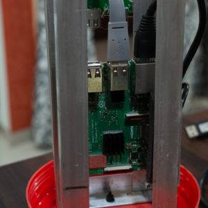
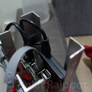
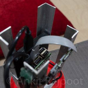
I mounted the USB hub on the back of the large aluminum bars using some hot glue. I am using a cheap non-powered USB hub which I modded to add external power to it. There is an excellent instructable by “msaleiro” that demonstrates how it can be done. The whole aluminum frame is fixed to the base using just two M4 screws. With everything mounted, it was time to connect the cables and route them nicely. Right now, there are three cables running out of a hole I drilled in the base: A CAT-6 LAN cable, and two USB cables. One USB cable powers the Raspberry Pi and the other powers the USB hub.

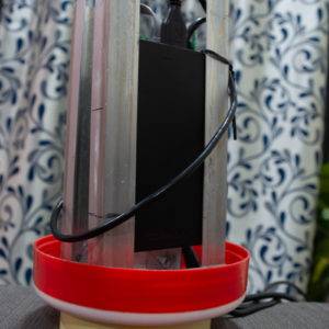
That’s all about the design. Now, some pictures of my build.
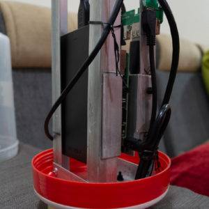
Build Pictures


Closing Thoughts

As you can see in the pictures above, the fan is missing because it’s on its way from China. I will update this post with new pics once I have that installed. But, before that, I would have to figure out whether to use it as an intake or exhaust. In any case, I would have to make some holes at the top of the outer shell. Also, the cable situation needs improvement. There are 3 cables coming out of the base right now. I want to keep it to a maximum of two: one for power and one for LAN. I am also exploring the possibility of fixing female LAN and micro USB connectors to the base. The base also needs some decent legs.

Even with all the shortcomings, I am pretty satisfied with how this build turned out. I initially wanted to wrap the outer casing with a carbon fiber vinyl wrap to hide the internals. However, now I kinda like the rugged industrial look of the whole setup. This enclosure is going to be running my raspberry pi media server until I get some time to work on the second version. One thing’s for sure, I like the cylindrical design and I’m going to keep it. I might decide to change the orientation though. I also plan to add LED lighting to the second version.

What do you think about this build?

If you liked this project, please share this post and leave your comments below. If you too decide to build something like this yourself, I’d really love to know more about it. Please share your story.

I regularly make and write about DIY projects. If you like what I share, please consider subscribing.

More Raspberry Pi Projects

Raspberry PI Based DIY Automated Irrigation System [With Pictures]

How-To: Make a Raspberry PI Based DIY Automated Irrigation System

How-To: Make a Raspberry PI Based DIY Automated Irrigation System

In this post, I will show you how to build an automated irrigation system using a Raspberry PI. It waters my garden automatically every 24 hours. And I can even control it over the web for on-demand watering. I will walk you through the three main components of this system: the plumbing, wiring the Raspberry PI and programming it.

I live in an apartment complex and like any average apartment dweller, I and my wife have built ourselves a little balcony garden. Because who doesn’t like waking up to a little bit of green, right? But, the flip side to keeping plants is that your travel plans are affected. In the past, we have tried more traditional options, with varying levels of success. Sure, you can leave a key with a helpful neighbor, but that might not be an option for everybody. We recently moved to a new house and did not have anyone to rely on, when we decided to go on a week-long holiday. In all the planning leading up the to trip, we almost forgot about this problem. About a week before the trip, we realized that we had no backup this time around. So I decided to do something about it.

We have about 10 large potted plants and 5 small ones. I wanted all of them to survive our week-long trip. I dived right into scoping the problem and designing a system to solve it.

The idea was to have a Raspberry PI control a relay board which could in-turn control a submersible AC water pump.

Parts needed

There can be innumerable ways to solve a problem. I chose my design based mostly on what I already had available in my parts bin. I have included Amazon links here to buy these items:

Electricals

  1. A Raspberry PI. I used a model 3B+, but even a Raspberry PI Zero W is more than enough for something like this. (Raspberry PI Zero W – Amazon IN, Amazon US)
  2. An 8G (16G recommended) microSD card. (Amazon IN, Amazon US)
  3. A 4 channel isolated relay module. (Amazon IN, Amazon US)
  4. A 5v 2A / 2.5A power supply. (Amazon IN, Amazon US)
  5. A portable charger with 2 outputs. (Amazon IN, Amazon US)
  6. Some jumper cables. (Assorted Jumper Wires 120pcs – Amazon IN, Amazon US)
  7. A 3/4 outlet power strip. (Amazon IN, Amazon US)
  8. A 12v fan. (Generic PC case fan 80/120mm – Amazon IN, Amazon US)
  9. A female micro USB plug. (Generic USB plugs set – Amazon IN, Amazon US)
  10. A plastic box to put everything in.

Plumbing

  1. An AC submersible pump. (Amazon IN, Amazon US)
  2. A container that can hold enough water. (Amazon IN)
  3. A garden hose long enough to cover the required area. (I used a PVC pipe because I wanted a permanent setup)
  4. Length of drip pipe and connectors. (Amazon IN, Amazon US and Amazon US)

The plumbing

I moved the 5 small indoor plants to the balcony to easy up plumbing. My initial thought was to hang a small plastic container from the ceiling and run drip pipes from it to each of the pots. To control the amount of water that flows through each drip pipe, they could be attached at different heights in the container. This would look something like below:

Plumbing design for an automatic garden watering system.
The original idea for the plumbing.

While this would have worked, there were two main issues with it:

  1. I wanted something a little more permanent, which I could activate in the future whenever need be.
  2. A plastic bottle with pipes coming out of it sticks out like a sore thumb. And it’s not good for a healthy WAF score.
DIY Project Feasibility Graph
Make sure you gauge your DIY project on this scale for financial feasibility.

So, I decided on a different approach: Running a 1-inch PVC pipe around the balcony rails, fitted permanently, and connecting the smaller drip pipes directly to it. This eliminated the need to have anything hanging from the ceiling, which guarantees a big improvement in the overall look and the WAF. With the plumbing plan finalized, I took measurements of my balcony and noted everything down. This is what the new arrangement looks like:

Plumbing design for a raspberry pi based automatic garden watering system.
New plumbing setup

I bought the necessary supplies as listed above and quickly fitted everything. Having a few tools helped. I cut the pipes to size using a handsaw and drilled the holes required for drip pipes. I attached the PVC pipe to the balcony using zip ties.

Once I had the plumbing setup finalized, it was time to move on to the second stage.

How to Wire the Raspberry Pi

I had a Raspberry Pi 3 Model B+ lying around collecting dust. So, I was planning to use that to implement the brains of this system. Raspberry Pi 3 B+ is a complete overkill for this project and something as humble as even a Raspberry Pi Zero W is more than enough to handle this. The plan was to use the PI’s GPIO pins to drive a relay board which in turn could control the Pump. All I needed now was to wire up the Pi with the Relay and think of how I am going to power both. I came up with a simple circuit as shown below:

Connecting a Raspberry PI GPIO to a relay module to control an AC appliance
Figure 1. Connecting Raspberry PI to a 4-channel relay module

A word of caution: Working with AC mains voltages can be dangerous if you are not careful. It might result in damage to your components or an electric shock. Seek qualified help if you are not comfortable doing this yourself.

The above circuit diagram connects physical pins 28, 3, 5 and 7 (GPIO 1, 2, 3, 4 respectively) on the Raspberry PI to pins IN1, IN2, IN3, IN4 on the relay module respectively (It’s a 4-channel relay module). I connected the AC water pump to the third relay. Notice, that the ground line of the mains supply connects to the relay module before reaching the water pump. This is how the relay controls the activation of the pump. The circuit between the two pins is completed when the relay is activated, and the pump turns on. Also connected to the relay module is a female micro-USB connector. This is so that I can power the relay using a standard micro USB cable, such as the one that charges your phone.

You can get detailed information on the pins of the Raspberry Pi by typing “pinout” on a terminal in Raspbian or going to www.pinout.xyz

Note: Relays handle high voltages on one end and are connected to low-voltage sensitive electronics on the other. The recommended way to connect a relay to a Raspberry PI is to use an optocoupler to isolate the two sides of the relay. You don’t see one in the above diagram because this relay module has one built-in. When buying a relay module, make sure to read the description to find if the relay is suitable for direct connection to a logic circuit such as Raspberry PI / Arduino. Most relay modules being sold on Amazon / AliExpress nowadays are.

I made the above GPIO connections using jumper cables and added two 5v power supplies (phone chargers) – one for the Raspberry PI and one for the relay module. I then wrote a small python script on the PI to test out the circuit, substituting the water pump for a bulb.

Connecting the Raspberry PI to a relay module
Raspberry PI connected to the relay module

Once this jerry-rigged proof of concept setup was tested, it was time to put this all in a bigger box and have all the components fixed securely, so they don’t bump into each other and set my house on fire. One of my major focus areas on this whole project was the idea of redundancy and fail-safes. I wanted this system to have a backup for some of the most common failures that I could think of.

One very common scenario was a power outage. Not that the device could do much if there was a power outage, but I still wanted it to have backup power at least for the Raspberry Pi. This was mostly driven by my fear of the SD card failing due to repeated reboots. So, I threw in an old, but functioning battery pack I had, in the mix and ended up with something looking like this in a new box:

Raspberry PI all connected up with battery pack

The battery pack has two outputs to connect two devices simultaneously. It was perfect for this purpose as I could connect both the Raspberry Pi and the relay module to the battery pack and did not have to worry about running 2 charging wires into the box. This also made the box a self-contained unit which could run itself for several hours to outlast any power outage. Now, at this point, you know that I have a 4-channel relay module, but the pump is only going to need one relay. So, I started thinking about uses for the other three.

All this while, one thing had me worried: all these electronics in a cheap plastic box could be a recipe for fire. So, I wanted to fix the whole setup outside the home in the balcony. Outside meant more heat during the daytime, which could mean that the Raspberry PI will run very hot in a closed box. So, I wired up one of the relays with a 5v power supply (from the battery pack) and connected it to a CPU fan that I fixed to the box lid. I also cut up various holes using a box cutter to pass wires and also for ventilation.

I scripted the fan to turn on when the CPU temperature hits 55*C. Once triggered, it keeps running till the CPU cools down to 45*C. With the fan attached, I now had 3 relays available to handle higher power AC currents. So I decided to hook up a generic extension board to it. The setup looked something like this after everything was wired up:

Full setup with the extension board hooked up


raspberry pi automatic watering system block diagram
Block diagram showing all components and connections (Click for high resolution)

A few things to note in the above diagram:

  1. I connected the wall charger to Slot 1 in the Extension board. I did not show this in the above diagram to reduce clutter.
  2. The cooling fan is a typical 12v PC cooling fan running on 5v. This does not harm the fan, it runs slow and is more than enough for the PI.
  3. Relays 1-3 handle high AC voltage and relay 4 handles 5V DC.
  4. I wired the setup in such a way that GPIO 1 on the PI controls Relay 1, which controls slot 1 on the extension board. Similarly, GPIO 2, 3 control slots 2 and 3 respectively and GPIO 4 controls the fan. This is to make identification easier during coding.
  5. The water pump can be connected to either slot 2 or 3.
  6. Slot 1 is an Active Low slot. i.e. when the relay signal is 0, this slot will have AC power. Other slots are wired the other way around – they only have power when the relay signal is 1 (high). This is a failsafe measure – in case the battery runs out (more on why that might happen in the software section), and the relay board and PI are turned off, the charger is turned on automatically and the system boots up again.

Relays and active-high vs active-low

A relay usually has 3 pins on the AC side. I have numbered them 1-3 in the image below for easy identification:

single relay module

The symbol denoted by K1 to the right of these pins explains how the internal circuitry is wired up in the relay. The white line connects Pin 1 and 2 in the symbol. This is the default state of the relay: pins 1 and 2 are connected when the relay is off.  This is the active low state of the relay. If you connect a power source and a load in series to these pins, the circuit is complete and the load would get power.

When the relay is turned on though, the connection between pins 1 and 2 will be broken and instead, pin 2 will be connected to pin 3. Now, pin 2 and 3 make up an active high circuit. Any load connected to pin 3 would turn on only when the relay signal is high.

Note that not all relays follow the same convention, so, before wiring anything up, take a look at its description and the switching diagram.


How to Program the Raspberry Pi

With everything wired up and packed decently, it was time to move to the next stage – the software to control everything. Just like with the electricals and plumbing, I had decided on the scope of the software too and come up with a list of functions I wanted:

  1. Run the pump reliably: once every 24 hours for 15 seconds.
  2. Ability to trigger the pump run remotely over the web.
  3. Keep a log of all times the pump was run in the past and serve that over the web.

Given that I had a little time and only really needed very basic features, I decided to code a solution myself instead of looking for something ready made. This might seem counter-intuitive at first, but it’s not. With any ready-made solution, I’d first have had to spend time searching for it. And even if I found something that fits my requirement, it would most likely have many other features that would add to the complexity and require testing. A tailor-made solution was not only easy to implement, given the relatively easy requirements, but it also fit better and more importantly, I knew the innards of it which provided me the confidence that I can leave this unattended for 10 days.

I decided to implement all the functionality as separate Python scripts. You can find the code and more details on how it works in this GitHub repository GardenPI. Clone the repository to play with the source code:

git clone https://github.com/ankitr42/gardenpi.git

I also wrote some crontab entries to run controller scripts either during boot-up or at regular intervals. For example, the web server and temperature run at boot up. While the pump controller runs every 30 minutes to poll the elapsed time since the last run. To view the crontab commands I used, see the crontab.md file in the repository. You can set up the same crontab on your PI by running crontab -e on a terminal.

I plan on further improving the GardenPI software and make it more generic so that it can fit a wide variety of use cases. At the time of writing this post, the software had the following features.

  1. Separate scripts to implement services that control pump, battery charger, and cooling fan.
  2. A small DB that keeps a log of each event happening in the system, such as pump runs, battery charger toggle, and fan toggle.
  3. The battery charge controller service toggles the charger on/off every 4 hours to avoid over-heating the battery and maintain a charge-discharge cycle. Note that this meant that there was a risk that the battery ran out before the service could turn the charger on. If that happens, the PI and relay would shut down and the slot 1 being an active-low slot, would automatically turn on the charger.
  4. A small web server that reports the status of each of the above service.
  5. The web server also allows running the pump on demand with the help of the pump controller script.

Please see the GitHub repository for more information on how you can use the code.

Admittedly, the software took the longest and the most work. It took 2 all-nighters to achieve the bare minimum functionality I was shooting for, work reliably. Managing a full-time job and DIYing on a time-table is hard. Finally, I was able to test the complete set up for 2 days before leaving and it worked flawlessly.

If you have any questions, let me know in the comments below. Or, if you decide to make this, share your story. If this post helped you, please share.


More Raspberry Pi Projects

DIY Custom Enclosure for Raspberry Pi Media Server

Google Drive Shared Folder Quota Issues

Google Drive Shared Folder Quota Issues

Recently, I ran into this issue with Google Drive where it wouldn’t let me upload content to a folder shared with me by a friend. This friend in question had lots of space available on his drive account and I was only uploading content worth a fraction of the available space. But every attempt to upload the files would fail with an error message: “Not enough storage quota to upload. Upgrade Storage”

Google Drive error message when uploading to a shared folder
Error message when trying to upload to a shared folder. Click for full-size image.

The friend that had shared the folder with me, had more than 12GB of available space in his account. And the content I was uploading to this drive was about 4GB. So, you’d expect it to work, right?

Any normal person would expect that since I was uploading to someone else’s shared folder, the data would count against their quota. So did I. But as it turns out, Google Drive has a very unique (or should I say weird) way of treating such cases.

How does Google Drive Compute A User’s Storage Quota

Google Drive calculates storage quotas based on the ownership of files. Where those files are actually stored, does not matter. Their size would count against the storage quota of the file owner irrespective of the upload location. And when you upload a file, obviously, you are assumed to be the owner of the uploaded file. Thus, no matter where you upload a file, you can never upload more data than your own account allowance.

You can view the ownership of any file by right-clicking it and selecting “Share”. In the resulting dialog box, click the “Advanced” link. The current owner of the file has the label “Is owner” to the right of their name:

Advanced sharing settings dialog showing current owner. Click for full-size image.

Google does allow you to change the owner of a file, if the file in question is a Google document, i.e., a Google doc, Google spreadsheet or a slide. To change the owner of such a file, click the Pen icon against the name of the person you want to make the owner and select the “Is Owner” option from the drop-down menu and click Save Changes. Google Drive will ask you for a confirmation and once you click Yes, the file’s ownership will be transferred.

Be careful while doing this though, because once you transfer the ownership of a file to somebody else, you will no longer be able to change it back unless that person does it for you.

Transfer ownership of a Google file.
Transfer ownership of a Google file. Click for full-size image.

Also, the above method is only applicable to Google file types. You cannot, for example, change the ownership of an image file.

Google must have their reasons for this behavior, but it’s very confusing from a user’s perspective, and reduces the usability of Drive. What’s the point of having cloud storage, if you cannot use it to collate pictures from friends?

To make matters worse, Google does not make this information easily available. I had to dig deep into Google’s consumer forum to find a clue. There I found other people facing the same issue and figuring stuff out on their own. So, I did some of my own experiments to confirm the theory and decided to document it all here in case this helps someone.
If this post did help you, consider sharing it with your friends.
If you like what I write here, subscribe to my blog so you will never miss a post.
Thanks for stopping by. Have a nice day. 🙂
How-To: Import WordPress blog into Blogger [With Pictures]

How-To: Import WordPress blog into Blogger [With Pictures]

If you are looking to migrate your blog from wordpress.com to blogger.com, then read the post below for a step by step guide.

Note: I have tested these steps only on blogs hosted on wordpress.com. But the steps will remain the same for WordPress blogs hosted on any hosting provider.

WordPress and Blogger use different data format when exporting blog posts and other blog data. This makes it difficult to seamlessly transfer posts and other content from one service to another. I faced the same problem when trying to move this blog from a WordPress domain to Blogger. While both the services use the same file format (XML), the underlying structure of data is different which causes Blogger to not recognize a file exported from WordPress.

If you try to import a WordPress export file directly into Blogger, the Import tool in Blogger will get stuck with the “Writing Blog Posts” message. If you are facing the same issue, read on to find the solution.

Blogger Import Get Stuck Trying to Import WordPress Content
Blogger Import Content Tool gets Stuck Trying to Import WordPress Content

I did some digging and found that the Blogger team had released a tool in 2010 to convert WordPress export files into Blogger compatible format. However, that tool is now long defunct. My search led me to another such tool online:

WordPress To Blogger Converter Tool

Using this tool, you can convert your WordPress export files into Blogger compatible format. After doing this, your files should import without any problems into Blogger. Read below for the step by step process with screenshots:

Step 1: Export Content From WordPress

  1. Go to your blog’s dashboard with an Admin account. You can access your blog’s dashboard by opening the URL <blog-name>.wordpress.com/wp-admin
  2. Locate the Tools section in the left navigation rail and click Tools > Export.
  3. In the Export page, you will see two options: Export and Guided Transfer. Click the Start Export button under the first section.
WordPress Dashboard Export Page
WordPress Export Page
  1. WordPress will ask you to select what you want to Export. You can select All Content to export everything including comments, media etc.
WordPress Export Content Selection
WordPress – Select Content to Export
  1. Click the Download Export File button.
  2. You will get a prompt to download an XML file. Save the file on your local storage.

Step 2: Convert Exported File to Blogger Format

  1. Point your browser to the WordPress to Blogger converter website.

WordPress to Blogger Converter Tool Interface

  1. Click the Choose File button and select the XML file you had downloaded from WordPress.
  2. Click the Convert button.
  3. And that’s all you need to do. Depending on the size of your XML file, the tool will take a few seconds to convert the whole thing to blogger format. Once the conversion is done, your browser will prompt you to download the converted file. Save this file with a different name on your local storage.

Importing the Content to Blogger

  1. Once you have the converted file, you will need it to upload to your Blogger dashboard.
  2. Start by logging into www.blogger.com with your admin credentials.
  3. Click Settings > Other in the left sidebar.

Blogger Import Tool

  1. Click the Import Content button under the Import & back up section on this page and select the file that you had converted earlier.
  2. Blogger will upload the selected file to the server and will import all elements present in the file to the server.

WordPress to Blogger Import Complete

  1. And that’s all. You have successfully migrated your WordPress.com blog to a Blogger blog.

I hope this guide helps someone who is facing the same problem. I recently moved my blog from WordPress.com to Blogger.com for multiple reasons which will make up for a good post detailing the differences between the two blogging platforms.

Did you find this post useful? Let me know your thoughts in the comments section.

How-To: Reset Your Dish TV HD Set Top Box for Better Performance [With Pictures]

How-To: Reset Your Dish TV HD Set Top Box for Better Performance [With Pictures]

Do you use a Dish TV connection? If yes, chances are that over time your Dish TV set-top box has slowed down so much that it takes multiple seconds for it to respond to even the simplest of remote commands like Vol+/-.
Changing a channel takes minutes, and loading the program guide takes forever. It becomes very frustrating when you are browsing channels as you can never be sure if your remote input was missed by the box or it is just happily sitting there processing an old command.

If you have faced this situation and wondered if there’s way to fix this, let me tell you that, yes there is a way to fix this. All it requires is to clear up the box’s cache and do a reboot to freshen it up. After you have followed these steps, your box should become significantly fast.
I have only tested this process on my “Dish HD+ Recorder” box, but it should work on any other dish box as well.

Disclaimer: I have only provided this information with the intention of helping fellow users. I am not responsible for any damage or information loss to your box or TV that may arise as a result of you following these steps.

Reset Dish TV Set-Top Box
This is my set-top box on which I successfully completed this process.

Prerequisite: Make sure that you have turned on your TV and set-top box both and your set-top box has completed the boot process. You can leave your set-top box on for 10-15 minutes before starting the process.

Step 1: On your set-top box remote, press and hold the “Menu” button. Keep it held until you see a menu on your TV screen that is titled “Installation Main Menu” or something similar.

Reset Dish TV Set-Top Box
Select the “System Setup” menu item.


Step 2: In this menu, select the “System Setup” menu item and press “OK”. This will bring you to “System Setup” menu screen.


Reset Dish TV Set-top Box
Select the “Erase EPG” menu item.

Step 3: In the “System Setup” menu screen, select the “Erase EPG” menu item and press “OK”. The system will display a warning message on the screen like below.

Reset Dish-TV Set-Top Box
Press “OK” on this warning screen.

Step 4: Click “OK” or one of the Color buttons on the remote as the message instructs. Once you press “OK”, the system will display a message informing that the erasing is in progress like below.

Reset Dish TV Set-Top Box
Erasing…
Reset Dish TV Set Top Box
Success message

Step 5: Once complete, the system will go back to the “System Setup” menu screen automatically. Here, you should select the menu item “Erase flash FS”.

Reset Dish TV Set Top Box
Select the “Erase flash FS” menu item.

Step 6: Once again, the system will ask you for confirmation like below. Confirm on this screen to proceed.

Reset Dish TV Set Top Box
Press “OK” on this warning screen.

Step 7: When Step 6 completes, the box will automatically reboot. This reboot may take several minutes to complete as the system will download the program guide and other data from the network. You will see a progress screen like this:

Step 8: Once the update completes, your set top box is ready to operate and is faster than ever.

If this post helped you, don’t forget to share it with your friends on your favorite social media platform. Have a good day. 🙂
Getting Cortana on Windows Phone 8.1 developer preview to work outsidethe U.S.

Getting Cortana on Windows Phone 8.1 developer preview to work outsidethe U.S.

For the last couple of months, fans around the world have been going crazy to try their hands on the latest update to Windows Phone. One of the most anticipated and most leaked features for the update was Cortana. Halo fans like me already loved her, and the rest of the world has fallen in love with her ever since the leaked videos surfaced. The tipping point was when Microsoft demoed the new update along with Cortana less than 2 weeks back on April 2nd. Ever since people have gone crazy to get the developer preview of the software. The good news, MS released the developer preview yesterday. And anyone can create a free App Studio account and get the updated.

But one of the bad news in the presentation on April 2nd was that the most loved personal assistant of all time, Cortana, will only be a US specific feature until late this year. Many were heartbroken; me included. Well, as it turns out, we don’t have to be disappointed since Cortana can be activated even if you’re outside the US. Just follow the following steps:

1. Go to Settings on your Windows Phone 8.1 device and look for the following two entries:
a. Language
b. Region

2. Tap language and then Look for English (United States). If you cannot find this, tap “add languages” and select English (United States) from the list. After installing the language pack, your language settings page should look something like this.

3. Now head back to the Settings page and tap “region”

4. Change Country/Region selection to Uthe United States and Regional format to English (United States) as shown in the following screen-shot.

5. Hit back until you reach the Start screen and reboot your phone.

6. Next time you hit the Search button, you’ll see the all dancing, all bubbly Cortana ready to assist you. Enjoy. If you have any queries, feel free to ask in the comments below.


Disk Cataloging Made Easy – CD Sync Portable

Disk Cataloging Made Easy – CD Sync Portable

Those who maintain a huge collection of CDs/DVDs know what a pain it becomes to find something from that collection. You have to insert each and every disk into your drive and then search for the desired item in each of them. CD Sync is designed to solve this problem. It is a disk cataloger which allows you to catalog all your disks so that you can search and browse the contents of your disks even without inserting them. The interface of the program closely resembles Windows explorer. Here’s a screenshot of the main window.

CD Sync Portable. Click for full-size image.

As you can see from the screenshot, the interface is exactly the same as Windows explorer. The list on the left site contains all the catalogs you have created. The catalogs are categorized into proper categories. Several categories come pre-installed with the program, and you can also create new ones, as and when you desire. When you select a catalog, its contents are displayed in the browser, just like in Windows explorer. Here you can browse the catalog simply by double clicking the files and folders. If the source disk of the catalog is available, you can simply click on an image / video / audio file and the built in previewer will give you a preview of the file’s contents.


CD Sync provides extremely powerful searching features. You can search for a single file or multiple files in any number of catalogs simultaneously. To begin a search, click the Search button on the toolbar or press F3. When you do that, you’ll see a new window ‘Search Results’ as shown below.

Click for full-size image.

The search window acts both as a starting point and the ending point of a search. Two buttons are available on the toolbar namely ‘Basic’ and ‘Advanced’ allowing you to perform basic and advanced searches through your catalogs. The basic search function lets you specify a filename and select the catalogs in which you want to search. The advanced search feature enables you to perform more advanced and content specific searches. For example, you can search your music catalogs for songs by a particular artist. When you perform a search, the result will be displayed in the Search Results window. Here also, if the source of the catalog is online, you’ll be able to preview the contents of the file.

Some of the other features of the program are:

    • Integration into Windows explorer: Simply right click any folder/disk/network drive and there you have the option to catalog your disk.


    • Portability: Just extract the portable version of the program into a usb thumb drive and start using it. No installation is necessary. Your catalogs go with you wherever you go.


    • Interoperability: The portable and non-portable versions of the program are interoperatble. Meaning, you can export your catalogs from one version and import them in the other.


    • Stores disks’ and folders’ file structure as it is, to allow you to browse and search them even when they’re not available.


    • Stores extended properties about each file. CD Sync can store above 25 types of properties about each file. This includes:
        • Standard file properties, like name, size, and date(s) etc.


        • Music properties, like artist name, album title, album year, and song title etc.


        • Document properties, like company, subject, and category etc.


        • Video and image properties, like width and height.


      • File icons for .ico, .exe, .scr, .cur files.


    • Incorporates powerful searching features that allow you to search any number of images at a time. It also features content specific search capability (for ex. You can search your music collection for all songs by ‘Linkin Park’.)


    • Allows you to export your images, in case you’re migrating to new PC and don’t want to create all those images again. This feature also comes in handy in case of data loss; you can always restore your images from the backup copy.


    • Several image categories (like Games, music movies etc.) are provided, so that you can categorize your images. You can also create new categories.


    • Allows you to export the file-list for an Image in XML format. From there, it can be read and interpreted by any other program.


    • If the source media of an Image is available, the built-in previewer allows you to preview almost all major types of audio, video, and image files contained in the image. The built-in previewer can also be configured to automatically play audio and video files as you select them in the file browser.


    • Features a clean and friendly Windows Explorer like interface. So that not too much of your time is wasted recalling where a particular command was located.


  • Allows you to set custom description for each and every file/folder in your image.